Colour -
Construction -
The power plant -
The machine guns -
Curving (bending) depron -
Second thoughts -
Flying (model 1) -
Flying (model 2) -
Exchange is no robbery -
Comments -
Conclusion
Colour -
Construction -
The power plant -
The machine guns -
Curving (bending) depron -
Second thoughts -
Flying (model 1) -
Flying (model 2) -
Exchange is no robbery -
Comments -
Conclusion
Parts of this may sound critical, but it's not intended that way. Nobody's perfect (least of all me) and every kit has its faults. Microaces kits have established a new way of doing things, using new materials, which experiemced modellers may struggle with. We now have a new expression: 'Crowdfunded'. This means that the product is funded by pre-orders before it is actually produced. Microaces take that a stage further by producing 'beta' kits which invite feedback to be incorporated in the final kit. They also produce 'pledge' kits which are bought and paid for before they become available. Years ago I produced R/C monitors on this basis and was told that it was illegal!
Their first kit was a Fokker DVII in several liveries. This is one of my favourite aircraft so I bought a kit in Urnst Udet colours. Since then they have produced kits for an SE5a, a Bristol Fighter, a Fokker Dr1 and a Fokker DVIII. A Sopwith triplane and and a DH2 will be next on the list. I didn't fancy the SE5a or the Brisfit (too many rigging wires) but ordered a Dr1 kit in Richthofen colours.
I don't know whether it's just me, but I have problems with the microaces website (www.microaces.com). It wouldn't accept my order for a DVII kit so I had to order by email. When I tried to order a beta DR1 kit it would not give me the beta discount (25%). When I protested, they suggested that I donate it to them (I hope they were joking). When I refused I was sent the pledge discount (10%). Another protest and I received just an apology. Yet another protest and I received another 5%. I was annoyed by now so I queried whether it was too late to cancel the order. They cancelled the order and refunded the balance of what I had paid - which wasn't what I intended. The biter bit, I now had to wait for the final kit and pay full price!
I was accused on the DVII kit of doing things my own way. With nearly 100 published kit reviews over the last 40 years, I would never do that. There is no point in reviewing something if you don't do things as the manufacturer intended. You will note the absense of the word 'review' from the above title, this is an adventure story. I did have misgivings about the triplane which is a difficult subject in so small a size, both for the designer and the builder. I think Microaces were brave to tackle it.
One feature of the Dr1 kit is that it has a fully detailed dummy rotary engine which requires a longer propeller shaft to go through it. These are produced by E-Flite for their PT17 (and others) but are hard to find. In fact Microaces are getting their own made. I couldn't source them in the UK but I ordered two from RC Planet (www.rcplanet.com) in Salt Lake City and got them in three and a half days! I hope there aren't a large number of kits out there just waiting for a propshaft!
That dummy motor is responsible for a lot of problems. Apart from the need for a longer shaft it moves the motor/gearbox and the battery further back on a model which is obviously going to be tailheavy anyway. Microaces intend that the motor should spin freely and have even produced a video to that effect. Personally, I don't understand why anyone would go to the effort of producing a dummy motor (and all of the problems which it leads to) and then not make it spin with the prop as per the original
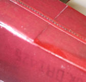
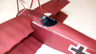
On a model made from depron, it is inevitable that there will be lots of unpainted edges showing. Most people seem to able to ignore this, but I can't. This was no problem with the DVII and I was able to touch up with paint where necessary (see here). However, it must be said that this was a beta kit and the production kits may be different. The Dr1 seems to use a different printing technique as used in magazines and newspapers, where the colour is made up of different coloured dots. One result of this is that the result looks like a metallic colour. This looks fine from a distance but, even if the colour is an exact match, paint stands out like a sore thumb. On the Richthofen Dr1 the cowl has to be painted and there is no way it can match the rest of the model. Microaces do try to disguise this by making the fuselage immediately behind the cowl very dirty. This isn't confirmed by photos of the real thing.
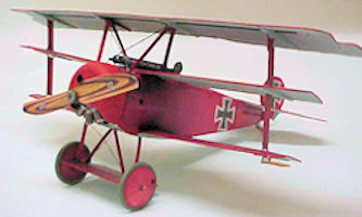
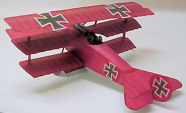
I immediately had a problem here because the kit complied with popular myth that the machine was all red. However, there is no doubt that Richthofens machines (all 5 of them) had sky blue undersurfaces. Add to that the fact that the kit was scarlet instead of the correct bright red. I decided that repainting the whole model was impractical so I settled for painting the underside blue (Humbrol No.65 acrylic). Surprisingly, this only added 0.9 grm. I didn't like the Balkan (straight-armed) crosses which adorned the machine in its final (fatal) form and replaced them with Cross Patee made with DIY waterslide transfer paper. I should point out that the order to change the crosses went out on 18 April 1918 and Richthofen was killed on 21 April. I should make it clear here that the Microaces kit is meant to represent Richthofens fifth and final machine 425/17. I can forestall any arguments here by claiming that my model represents Richthofens third machine 477/17 in which he scored most of his triplane victories (12).
I'm jumping ahead of myself here, but before I describe the kit I did have some problems and relayed feedback on them to Microaces (which I wasn't obliged to do). Their reply was that it was my building. Fair enough, I make mistakes like any other mortal. The only way to settle the matter was to make another one, so I ordered another kit in Herman Goering livery. The logic here was that it would be fairly straightforward to modify the kit to represent Richthofens second machine 152/17.
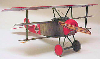
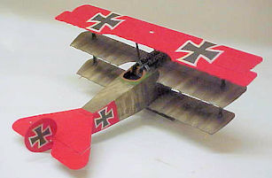
152/17 had the standard stripey green/purple scheme with blue undersides and with the upper surface of the top wing, the tail, cowl and wheels painted bright red. The Microaces kit represents Goerings machine as virtually standard with a white tail. It is in a stripey brown/green finish (anyone care to tell the difference after 100 years?). The blue underside and white tail had that metallic sheen described above and appeared as two shades of silver! It had Balkan crosses.
So, once again I had a problem. Do I accept things as they are, or do I attempt to repaint the whole model with a consequent increase in weight - mostly in the wrong place, behind the C of G. I knew I could paint the underside blue with a weight penalty of less than a gram. I could dry brush the rest of the model in green/purple for about the same. The problem was the red parts. I could find matt crimson easily but not matt bright red. I thought of using gloss red and overspraying with matt varnish, but that really would add too much weight. I decided to just paint the red parts and leave the rest of the model. If the worse came to the worse, I could always use crimson. At least I would get rid of the exposed depron edges. I already had DIY waterslide transfers for the crosses.
I tried mixing mixing crimson with white but was rewarded with orange. I tried satin signal red, but that gave variations with the brush marks. So, I ended up with crimson. Now red, crimson, etc. is a transparent colour and putting over the original stripey green colour made it darker. I knew that Richthofen's Albatros' were paimted red over the original colours and crosses with the crosses showing through. Therefore, It made sense that the same thing might apply to his triplenes. Yes, photos do show that the crosses were applied over the red, which I was doing anyway.
Previous kits have featured a superb construction manual (not supplied with the kit, you have to download it from their website). This had lots of exploded drawings which showed exactly where everything went. It also had drawings of all the parts which made them easy to identify. Sadly, the Dr1 isn't up to this standard, though quite adequate. An exploded view of at least the inner structure would help. I do feel that anyone who hasn't built one of these kits previously may struggle.
The wings, like all microaces kits, are a section similar to the Jedalski section with a crank at about one third of the chord. This is supported by ribs which have a sticky attached to match the wing colour. This works well with no exposed depron visible. The sticky material is superb and stays attached. It also goes around sharp corners without problems. On my first model I assembled the wings and tail so that I could weigh the result after painting. The tail is reinforced with a strip of carbon along the front of the elevators. This is barely adequate and a round rod would be better. Experience of three models now prompts me to add an extra piece to avoid the elevators becoming misaligned.
The fuselage has a core frame of 1.5mm depron with the 1mm depron skin wrapped around it. This skin comprises the two sides, the rear top decking and the rear bottom all in one piece. Here is where the problems started because 1mm depron is very resistant to curving. The recomendation is that you score the inner surface at intervals. At best, this produces a lumpy curve. Where there is a sharp bend from the side to the rear decking it really doesm't work at all. On the DVII kit the rear decking is separate which helps, but it really needs an extra former at the half way point.
The Dr1 also needs another former to space out the sides and support the becking. Without this the decking can collapse and push the sides out. I made this point on the DVII kit and Microaces agreed with me, but did nothing.
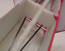
So, I decided to separate the decking and attach it separately. Likewise, the bottom is attached only at a small point along one side and it made sense to separate that too. This made it a simple matter to assemble the fuselage in a conventional manner and add the radio gear without any problems. I was wary here because I had problems with the DVII kit due to the thin wire pushrods fouling the formers. This continued to be a problem until I performed major surgery. Therefore, I decided that I would use carbon pushrods on the Dr1. I was glad I did this because I had to cut away a lot of the former at the leading edge of the tail. Had I used the wire pushrods supplied, this would have been a major problem.
The fuselage sides are curved at the front to blend into the round cowling. This is done by scoring the inside surface. Originally it was recommended that you do this with a scalpel blade. Later instructions suggested a ball point pen. I think the pen is better but neither is really effective. On the real Dr1 there is a very obvious fold along a stringer and I scored and folded the sides to match. By using UHU 'Por', which is a contact adhesive, I was able to attach the sides to the front former. On both models, the front of the sides didn't match up with the firewall. The result was that there was downthrust (no bad thing) and the sides had to be trimmed to suit. Funnily enough, the bottom was exactly the right length, but too narrow.
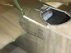
Fitting the tailplane produced another problem. If you fit the tail in the intended position as determined by the cutouts in the tail against the fuselage sides, the elevator hinge line is forward of the end of the fuselage side, which means you cannot obtain any down elevator unless you cut away the side. If you fit the tail in the obvious position with the hinge in line with the rear of the fuselage (lining up with the cutaway in the rudder) you leave an unprinted portion of the tailplane showing (see later).
Before I attached the decking, I made up an axtra former to go midway along the decking for the reasons given above. The width was determined by measuring the appropriate point on the fuselage bottom. When I fitted the decking, it was too narrow at the front. While the fuselage bottom fitted at this point, the part that went under the lower wing was also too narrow. All of this coincided with the former at the rear of the cockpit. It seems obvious that this former is slightly too wide. Instead of attempting to curve the decking by scoring it, I steamed it around a suitable former. I'll describe this process later.
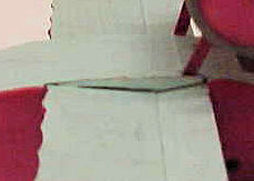
The top decking was too narrow, requiring some filling. The fuselage bottom below the wing was
The lower wing halves are joined at the correct dihedral by means of a jig and a structure which goes below the wing. When I had fitted the lower wing to the fuselage and came to add the part of the fuselage bottom which went below the wing, I found that this was too narrow, particularly at the nose. What's more, the pressure against the structure below the wing removed most of the dihedral. I decided at this stage that fitting the interplane struts would correct this (see later).
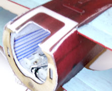
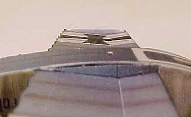
After fitting the mid wing, the polypropelene cabane struts are fitted to a platform (the radio receiver/servos are attached below this platform). Then the front decking can be added. This fitted against the nose perfectly, but the rear didn't line up with the rear decking at all. By reducing the height of the two formers behind the wing, I was able to make the front and rear decking meet, but with a triangular gap..
The front decking would not line up with the rear. Reducing two formers
The second model looks awfully familiar.
One thing about Microaces kits which I will criticise is the use of thin wire pushrods. Their earlier range of kits used these running in tubes, which would work well. On their current range the wire is totally unsupported. On some kits, the wire is even bent to go around formers. On my DVII kit there was a lot of lost motion, particularly in the elevator, which made the model almost unflyable. I eventually improved this by cutting off the rear of the pushrod and inserting a tube for most of the length and then remaking the rod. There was still a small amount of lost motion which gradually got worse. I eventually resolved this by cutting the fuselage open and securing the tube to the formers. On both Dr1's I replaced the wire with 1mm diameter carbon rod. It was necessary to cut away a fair amount of the former at the front of the tailplane to clear these rods. If this wasn't done with the wire rods it would cause lots of problems. It justified my fitting the top decking separately.
The undercarriage is very similar to that on the DVII, which works well and can take a lot of punishment. The wheels are made up of several layers of depron with rubber tyres. The instructions tell you to glue the wheels to the axle, but I made them rotate separately. Maybe they were right because, on a smooth floor, it will only ground loop.
It only remains to fit the top wing to complete the airframe. With all of these kits, the wing is balanced on a set of struts. It is very easy to get the wing misaligned (no fault of the kit, blame the full-size designer). Wary of the problems I created for myself with the DVII, I made sure that the wings were parallel to each other and attached the top wing to the cabane struts. I then slid the interplane struts through the slots in all three wings and checked the dihedral. No, they didn't return the lower wing to the correct dihedral (you guessed). What I had was a top wing with very slight dihedral, a mid wing with no dihedral at all and a lower wing with about half the intended dihedral. There didn't seem to be a lot that I could do about things at this stage, so I glued the struts in place and pressed on with the cowl, motor/gearbox and dummy engine.
I did intend to fly the model in this form and see what happened, but my restricted mobility and bad weather meant that this was delayed for some time. This gave me time to think about a solution and the obvious thing to do was to cut through the interplane struts below the top wing and rejoin with an overlap. This would pull the the mid and lower wing up and increase the dihedral. It brought the lower wing up to match the dihedral jig, with the mid wing somewhat less. Only flying would see whether it worked (see later).
I decided, on the second model, that the only way to check whether the fit of parts was my problem was to do things as the manufacturer intended. I made up the fuselage skin in one piece with the various edges bevelled as described. To help with the sharp bends between the sides and the top decking I scored on the inside and then bent in the opposite direction to the score and bevelled what I could of the inside edges. This is fairly difficult as you must avoid removing too much and separating the parts. After steaming the curve into the rear decking and the front of the sides, I wrapped the skin around the former (D4) at the rear of the cockpit. You guessed - it fitted!
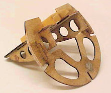
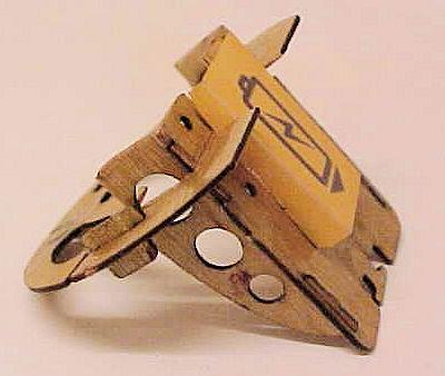
One change on the Dr1 from the DVII is that the keel (it's not a boat but I can think of no better name) is made from thinner material (1.5mm?). Curiously, while the first kit went together quite nicely, the second kit had slots in the various formers which weren't quite wide enough which meant that they have to be forced into position which deformed them. Several of the slots had to be elongated. One or two slots were too big. The keel is supplemented by polypropelene strips attached to the bottom edge (not necessary in my view), but the formers aren't made to fit this, which makes matters worse. Be aware that some of the formers have locating tags that can be mistakenly cut off as part of the support. This is where an exploded diagram would have been invaluable.
Now, There is a puzzle here. On the first kit the keel and formers went together beautifully but there were problems fitting the skin. On the second kit the keel had problems, but the skin fitted. I've already noted that the tailplane was a poor fit on the first kit and left an unprinted section. On the second kit it fitted perfectly, except that the keel projected behind the end of the sides (I cut this off). It's probably unfair to build two identical kits and compare them, because anybody's building can vary. However, the only difference is in the decoration and the method of production, whether it be laser cutting or stamping out, should be identical. Let's put it down to the Mandela effect.
On both kits, there was a difference between the front end of the sides and the firewall. There was downthrust (not a bad thing) on the firewall and the sides had to be trimmed to fit. Consequently, the sides didn't reach the rear end of the keel as already noted. At least, this explained the problem with the first kit. However, the fuselage bottom in front of the lower wing still wasn't wide enough.
All of this boils down to the assembly of the fuselage. This is complex and, as I said above, Microaces were brave to tackle it. Add the lower and middle wings to the mix and it must have been even more difficult.
On the second model I went to great lengths to ensure that I maintained the intended dihedral on the lower wing. The fuselage bottom needs to have a curve below the wing to accomodate the structure under the wing. In fact, the pieces which fold up to fit under the wing mean that it stays straight and tends to remove the dihedral. I fixed that by removing the structure under the wing after gluing the wing to the fuselage. I then added the middle wing which adopted the same dihedral as the lower wing. Trying the interplane struts, they fitted perfectly.
When I came to fit the top wing it became clear that the problem with the first model lay not in the length of the interplane struts, but rather the cabane struts. These are folded up from polypropelene and there is some variation in just where you fold them. The front strut has a pad whish is attached to the platform which accomodates the radio. The rear strut goes through a hole in the middle wing and is free to find its own length until you glue it.
On the first model I mounted the top wing on the struts and assumed that all would be well. I've already mentioned that the top wing on all these kits are balanced on a set of struts and there is considerable scope for variation. I can see no way that this can be made foolproof or self-aligning.
On the second model I did things differently. I made the cabane struts as long as possible by bending the pad at the bottom of the front strut as close to the pad as possible. I then added a spacer from 1mm depron to go under the pad. That way, I grabbed about 2mm extra length. I then cut off the outline of the root rib from the top of the strut, leaving just a tab, which I extended with spare polypropelene. This meant that the height of the wing was no longer determined by the struts. I then attached the top wing to the interplane struts and finally glued the tab on the evtended cabane struts to the centre rib. That left me with the top wing flat and the other two wings with the correct dihedral. The conclusion of this is that either the interplane struts are too long (model 1) or the cabane struts are too short (model 2).
The forward top decking fits over the centre wing. On the second model I did a trial fit without the wing and modified the gap for the wing. However, with the wing in place I couldn't make the decking line up with the rear decking without reducing the height of two formers. I then still had gaps to fill.
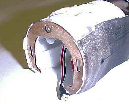
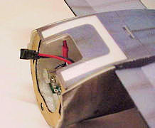
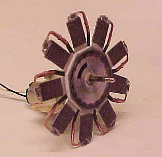
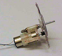
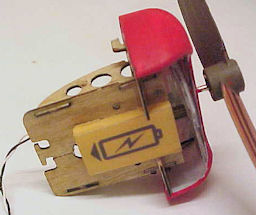
This incorporates the motor/gearbox unit originally used on the Parkzone 'P51' (and others). It requires a longer propshaft as used on that companies 'PT17' in order to pass through the dummy motor. The ply firewall has a ply frame that extends back into the fuselage and supports both the motor/gearbox and the Lipo battery. Note that all this is behind the firewall. The only thing in front is the dummy motor and the plastic cowling. This may strike you as an odd arrangement for a model that was obviously going to be tailheavy anyway. All of the WW1 machines had short noses because power units were heavy. The Fokkers, in particular, tend to make tailheavy models.
This whole unit is attached to the front of the model by means of two lugs which locate in the front of the model by rotating the whole nose assembly anticlockwise. You remove it by rotating clockwise - exactly the way that starting torque will rotate it! Remember electric motors produce maximum torque at minimum speed? The unit is retained in place by two magnets. Why not one magnet and a steel washer?
This could be a problem but the solution is simple. Reverse the firewall and the two formers at the front of the fuselage and you can install it by rotating clockwise. Then the starting torque will tend to tighten it, not loosen it. The two locating lugs are the first things that break in a crash. Fortunately, the kit contains two spares. Full marks for that one. The reason why the whole nose is removable is so that you can fit/replace the battery.
The instruction manual does point out that noseweight may be needed and suggests that you mount it below the firewall - close to the C of G. I needed a fair amount of weight and added it inside the front face of the cowl - as far as possible away from the C of G. The C of G is meant to be on the crease in the top wing. This is quite difficult to check, because it's so far above the centre of gravity. I could only get 3 grm of weight in the available space and I was sure this wasn't enough.
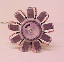
The dummy motor is made up of laminations of depron together with that wonderful sticker material. This is simple and effective and looks just the part. It may need balancing.
I used parts of the dummy motor to produce a profile.
I modified the ply parts to move the gearbox and battery forward.. On the second kit I used the centre of the motor parts, plus the cylinder stickers to produce a profile dummy motor. Then I modified the ply parts of the nose so that I could move the motor/gearbox forwards. I then glued the profile motor on to the main gear of the gearbox (I needed a small spacer to clear the pinion). With careful positioning, I was able to move the gearbox 1/4" further forward without the cowl fouling the profile motor. The battery mount moved forwards along with the gearbox. This meant that I could use a chunkier shaped battery to help to keep the weight forward. A bonus of this was that I could change the battery without removing the nose.
Sad to relate, all this effort was probably wasted because I still needed a lot of noseweight.
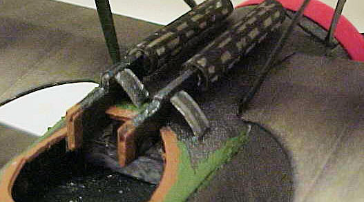
The worst part of any Microaces kit, after the wire pushrods (just my opinion), is the machine guns. I cannot see the point of using a transparent straw to represent the cooling jacket and then cover it with an opaque sticker. The holes in the jacket are represented by white blobs. Add the fact that the straw is overscale and the stock is just a profile, and the whole thing sticks out like a sore thumb. Obviously the size is decided by the size of the available straw. Why not use a solid rod and it could be made scale size. On the first Dr1 kit I improved matters slightly by thickening the stock by sticking the supplied parts each side of some spare 1mm depron. I replaced the gun barrel with a piece of 1mm diameter carbon rod. This removed the profile aspect but left those awful cooling jackets. I resolved that the second kit would be different.
First, I reduced the size of the straw by slitting it along it's length and gluing together round a smaller former. Then I used a bow pen to add parallel lines along the jacket with gunmetal colour paint (Humbrol No 53). Finally, I added bits between the lines, leaving 'holes'. It's probably nowhere near scale, but it looks 1000% better. My opinion, of course. Next time I'll remember to spray the straw with matt varnish first.
I'm not sure the difference was worth the effort.
I've mentioned that many parts of these kits require the fuselage skin to be curved. The recommended method is to score the inner surface at intervals with a scalpel blade or ball point pen. This doesn't work for me (the pen is slightly better). However, there is an alternative. First you find an appropriate fomer. A small paint tin works well. You then lay a piece of wet kitchen towel (or wet handkerchief) on the depron and lay the depron on your former. Then you use an electric iron (preferably a sealing iron) and iron the depron around the former. You need to hear the hiss of steam being generated. Don't be tempted to use a steam iron alone, you will melt the depron. This technique can be used to remove dings or dents from any depron model.
The real Dr1 had a very noticeable stringer line along the side of the fuselage. I managed to duplicate this by scoring and folding along the required point. The longest line on the included scoring diagram is about right.
I reached a point on the construction of the second model where I came close to scrapping the whole thing. The only reason I was building a second model was because my problems with the first model were blamed on my building. I then had exactly the same problems with the second model. Despite my efforts in reducing the structure under the bottom wing, when the fuselage bottom under the wing was added, all the dihedral disappeared.
The points where the tail pushrods emerge from the fuselage are already cut. The one for the rudder is way out of position. Thanks to the fact that there is no exploded diagram, on the first model I missed the point that the rudder has two hinges. There is a sticker as with the DVII but there is also a polypropelene hinge. On the first model I used just the sticker and things worked despite the pushrod exit being wrong. On the second model with two hinges the rudder was so stiff that the servo struggled to move it. With the awkward pushrod exit, it could hardly move it at all.
The missmatch of the fuselage bottom under the wing, meant that I needed to paint exposed depron edges and the was no way I was going to match the silvery blue colour. Maybe I should have painted it blue as with the first model.
I decided at this point to shelve things at least until I had made the first model fly.
Having corrected the dihedral as above, the first chance to fly was at an indoor meeting. Unfortunately, it proved impossible to take off from the smooth polished floor. All it would do is ground loop. In desperation, I hand launched the model and it dutch rolled quite violently and dived onto the floor. Fortunately, there was no damage. I decided at this stage that there was no point in completing the second model until I had sorted this one out.
The ground loop was a fairly easy thing to fix. I had the same problem with the DVII and resolved it by replacing the carbon axle with wire (carbon makes a poor axle because it is not a smooth surface). Also, you really need a small amount of toe-in, which you cannot achieve with carbon.
So, back to the dihedral jig. The above modification worked at the time, but by the time I had got to flying, the the top wing had bent down resulting in anhedral on the top wing and still less than the intended dihedral on the bottom wing.. Another rethink and I added a 1mm diameter spar onder the top wing at the crease so that the top wing would stay straight.. Then I adjusted my joint in the interplane struts so that I had the intended dihedral on the bottom wing. The dihedral on the midwing lay somewhere between the two. The photo in the manual suggests it should be the same as the low wing.
It balanced well behind the suggested positiom but adding more weight would need major surgery. I decided to delay this until I had another attempt at flying.
Finally, a calm mornimg appeared (no, the moon wasn't blue) and I was able to fly the model in a small garden area close to my home. It immediately became clear that the model was very sensitive to rudder trim and it took 5 short flights before it would fly straight and dutch rolling. All symptoms of tailheavyness. The problem was where to put more noseweight. At least I could now finish model 2.
After some thought, it was evident that I had to find some way to add more noseweight in order to establish the correct C of G. The easy way to do this was to add Blu Tack to the outside of the nose. When suspended from the crease in the top wing the model hung tail down. I added Blu Tack to the nose until the model hung level, then weighed the extra weight. Ouch! 4 grm. The prospect of adding a total of 7 grm noseweight to a 12" span model didn't appeal to me. I have complete R/C models that weigh less than that. However, I learned many years ago that the correct balance was more important than the weight.
I decided to apply some science(?) to the situation. The general rule for calculating the C of G of a multiwing model is to measure the distance from the leading edge of the foremost wing to the trailing edge of the rearmost wing and treat it as one wing. On the Dr1 that is 62mm. Normally you would make the C of G between 25 - 30% of the wing chord, i.e 15.5 - 18.6mm. Microaces recommend that the C of G should be on the crease of the top wing. This is 17mm from the leading edge - 27.4%. I can't argue with that so 7 grm it is.
My next attempt at flying the model was with 4 grm of Blu Tack stuck on top of the nose. I also set dual rate on the rudder to give me a choice of 100% - 70% - 50%.
Back to my garden site. I now had a model which flew nicely but rather fast, I settled on a compromise and reset the rudder rate to 60%.
Flying weight (with 7 grm noseweight): 46 grm.
I started by doing the sane excercise that I did with model 1 and added Blu Tack to the nose until the model hung level. Here I needed 4 grm which means that my excercise in moving the motor/gearbox and battery forwards saved me 3 grm. Judge for yourself whether it was worth the trouble.
I solved the problem of the stiff rudder by cutting it off and rehinging with mylar. Again with 4 grm of added noseweight and 60% rudder throw the model flew well (and noticeably slower).
Flying weight (with 4 grm noseweight): 35.5 grm.
Quite why model 2 was a whole 10.5 grm lighter than model 1 is a mystery. Moving the motor and gearbox forward can't account for all of that.
I now had the problem of how to add the extra weight to both models. First I swapped the cowls. The cowl of model 1 already had 3 grm of solder added to the inside of the front face. It was easy to find room for another grm of Blu Tack.
Model 1 now needed a whole 7 grm added and I added thia inside the dummy motor by removing the printed part from the front face of the crankcase, removing one layer of depron and replacing it with a spiral of solder, then replacing the printed part. The gyroscopic effects should be interesting - just like the fullsize.
The layout of this particular machine guarantees that it will be tailheavy. It's no coincidence that many of the full-size replicas have longer noses. You will need noseweight and as far forward as possible.
On the Dr1 (like the DVII kit) the keel is too long. If you fit the tailplane with the hinge line level with the end of the keel, the tailplane will not fit the cutout at the rear of the fuselage side. If you fit the tailplane to suit the cutouts, the hinge will be forward of the end of the keel and you will not be able to apply any down elevator. The solution is to cut off the end of the keel to match the fuselage sides.
It is important to preserve the dihedral on the lower wings. This is complicated by the fact that there is a mismatch between the lengths of the cabane and interplane struts. You will either have to shorten the interplane struts or lengthen the cabane struts (about 3-5mm). I would suggest that you set the lower wing dihedral, using the jig, and then glue it to the fuselage. Then pack between the keel and the wing as necessary to preserve the dihedral and remove the structure under the wing. The fuselage bottom will apply pressure to the structure and tend to remove the dihedral. The bottom is a little narrow at the rear and more narrow at the front.
What happens if you leave the underwing structure in place.
The alignment of the wings on all Microaces kits is critical. Don't assume that this automatic. Get it right and it will fly well.
The wire pushrods and the carbon axle don't work for me.
I now have two DR1's when I only wanted one. One has a performance more akin to a jet fighter than a WW1 triplane but, at least, it flies.
I said at the beginning of this narative that it should not be taken as criticism. Microaces may not be making history (as they claim) but they are changing things - and for the better. When I compare these kits with the rubber driven freeflight scale models I grew up with in the 1940/50's, there is no comparison. They are ingenius (some would say challenging), lighter, stronger and electric powered with radio control! There is nothing in these kits that need bother the serious modeller. How the rest of the world sees them need only bother Microaces.
I hope these notes have helped someone. They were prepared over a period of time and I apologize if they are over repetitive.
Models 1 and 2.
Construction
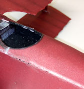
also too narrow. When this part reached the nose, it was much too narrow. Note the metallic sheen.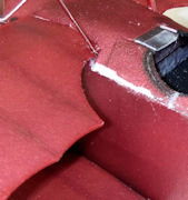
helped but left a triangular gap, which I filled with spare depron.
The power plant
The machine guns
Curving (bending) depron
Second thoughts
Flying (model 1)
Flying (model 2)
Exchange is no robbery
Comments
Conclusion
![]()
![]()